
The Clapper, recreated: lights that turn on when you clap
Clap once and an LED turns on, clap again and it turns off. A microphone, two transistors and one flip-flop chip.
Free build sheet
The parts, every wire with its length and bend points, a bend guide, both sides of the board and checkboxes to track your progress. Print it or keep it open at the bench.
Open the build sheetWhat you need
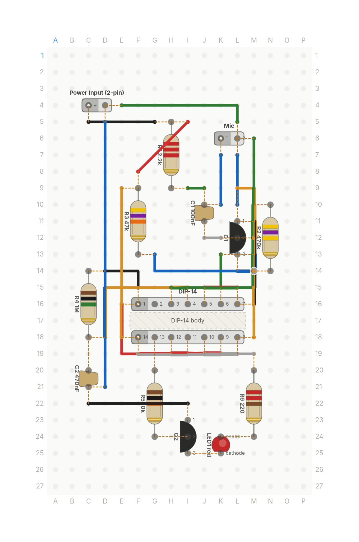
14 parts on a perfboard 16 × 27 holes, plus hookup wire.
| Qty | Part | Where to buy |
|---|---|---|
| 1 | Ceramic Cap100nF C1 | Buy Ceramic Cap on Amazon |
| 1 | Ceramic Cap470nF C2 | Buy Ceramic Cap on Amazon |
| 1 | Power Input (2-pin) J1 | |
| 1 | LEDred LED1 | Buy LED on Amazon |
| 2 | NPN Transistor (TO-92) Q1, Q2 | Buy NPN Transistor (TO-92) on Amazon |
| 1 | Resistor (axial)2.2k R1 | Buy Resistor (axial) on Amazon |
| 1 | Resistor (axial)470k R2 | Buy Resistor (axial) on Amazon |
| 1 | Resistor (axial)47k R3 | Buy Resistor (axial) on Amazon |
| 1 | Resistor (axial)1M R4 | Buy Resistor (axial) on Amazon |
| 1 | Resistor (axial)10k R5 | Buy Resistor (axial) on Amazon |
| 1 | Resistor (axial)220 R6 | Buy Resistor (axial) on Amazon |
| 1 | Electret Microphone U1 | |
| 1 | DIP-14 U2 |
Check every pin against the datasheet of the exact part in your hands before wiring.
As an Amazon Associate I earn from qualifying purchases.
Cut list
24 wires, 568 mm (22.4 in) in total, in the order the build sheet cuts them. Wire numbers match the build sheet. Each length includes 5 mm per end to go through the hole.
| Wire | Colour and net | Length | ||
|---|---|---|---|---|
| 6 | BlackPULSE D14 → F15 | D14 → F15 | 18mm | 10mm (90°) |
| 12 | BlackVCC G5 → C5 | G5 → C5 | 20mm | Straight |
| 18 | BlackGND M11 → M16 | M11 → M16 | 23mm | Straight |
| 24 | BlackGND C22 → I22 | C22 → I22 | 25mm | Straight |
| 5 | BlueMIC K10 → K7 | K10 → K7 | 18mm | Straight |
| 17 | BlueGND L7 → L10 | L7 → L10 | 18mm | Straight |
| 11 | BlueCLAP M13 → G13 | M13 → G13 | 30mm | 8mm (90°), 23mm (90°) |
| 23 | BlueGND D5 → D21 | D5 → D21 | 51mm | Straight |
| 4 | GreenMIC I9 → J9 | I9 → J9 | 13mm | Straight |
| 10 | GreenCLAP K13 → K15 | K13 → K15 | 15mm | Straight |
| 16 | GreenGND E4 → L5 | E4 → L5 | 30mm | 23mm (90°) |
| 22 | GreenGND M6 → H15 | M6 → H15 | 46mm | 28mm (90°) |
| 19 | RedGND L15 → J15 | L15 → J15 | 15mm | Straight |
| 1 | RedTOGGLE K19 → H19 | K19 → H19 | 18mm | Straight |
| 13 | RedVCC I5 → F8 | I5 → F8 | 21mm | Straight |
| 7 | RedPULSE E16 → I19 | E16 → I19 | 28mm | 13mm (90°) |
| 3 | WhiteBASE K12 → J12 | K12 → J12 | 13mm | Straight |
| 9 | WhiteCLAP M14 → L14 | M14 → L14 | 13mm | Straight |
| 21 | WhiteGND L19 → J19 | L19 → J19 | 15mm | Straight |
| 15 | WhiteVCC F19 → M19 | F19 → M19 | 28mm | Straight |
| 2 | YellowBASE M10 → M12 | M10 → M12 | 15mm | Straight |
| 8 | YellowTIMER D18 → I15 | D18 → I15 | 30mm | 13mm (90°) |
| 14 | YellowVCC E9 → E18 | E9 → E18 | 33mm | Straight |
| 20 | YellowGND L9 → M18 | L9 → M18 | 35mm | 8mm (90°) |
About this build
A hobby recreation of the clap switch effect made famous by The Clapper: clap once and the light turns on, clap again and it turns off. This is my own circuit, not the one inside the commercial product, and it switches an LED, not a mains lamp.
An electret microphone picks up the clap and a 2N3904 NPN transistor amplifies it. A CD4013 dual D flip-flop does the rest. The first flip-flop is wired as a one shot: the clap sets it, and a 1M resistor with a 470nF capacitor resets it about a third of a second later, so the whole noisy burst becomes one clean pulse.
That pulse clocks the second flip-flop. Its inverted output feeds its own data input, so it flips on every clap and holds. A second 2N3904 drives a red LED through 220 ohms from 5V. The parts library has no microphone, so the video draws one in the Footprint Editor first, from the CUI (Same Sky) CMA-4544PF-W datasheet.
The Clapper is a trademark of its owner. This build is not affiliated with or endorsed by them.
More builds
See all builds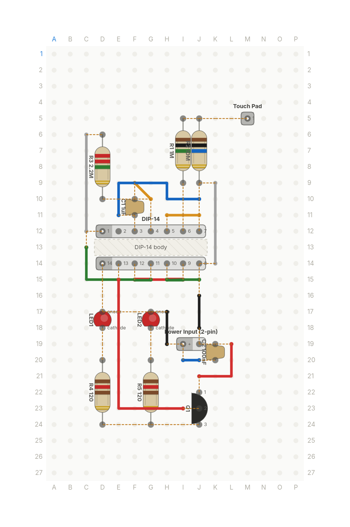 Premieres Oct 11
A lamp you turn on by touching it
Tap a metal pad and two white LEDs turn on, tap again and they turn off. One flip-flop chip and a MOSFET.
13 parts · 13 wires
LightsSensors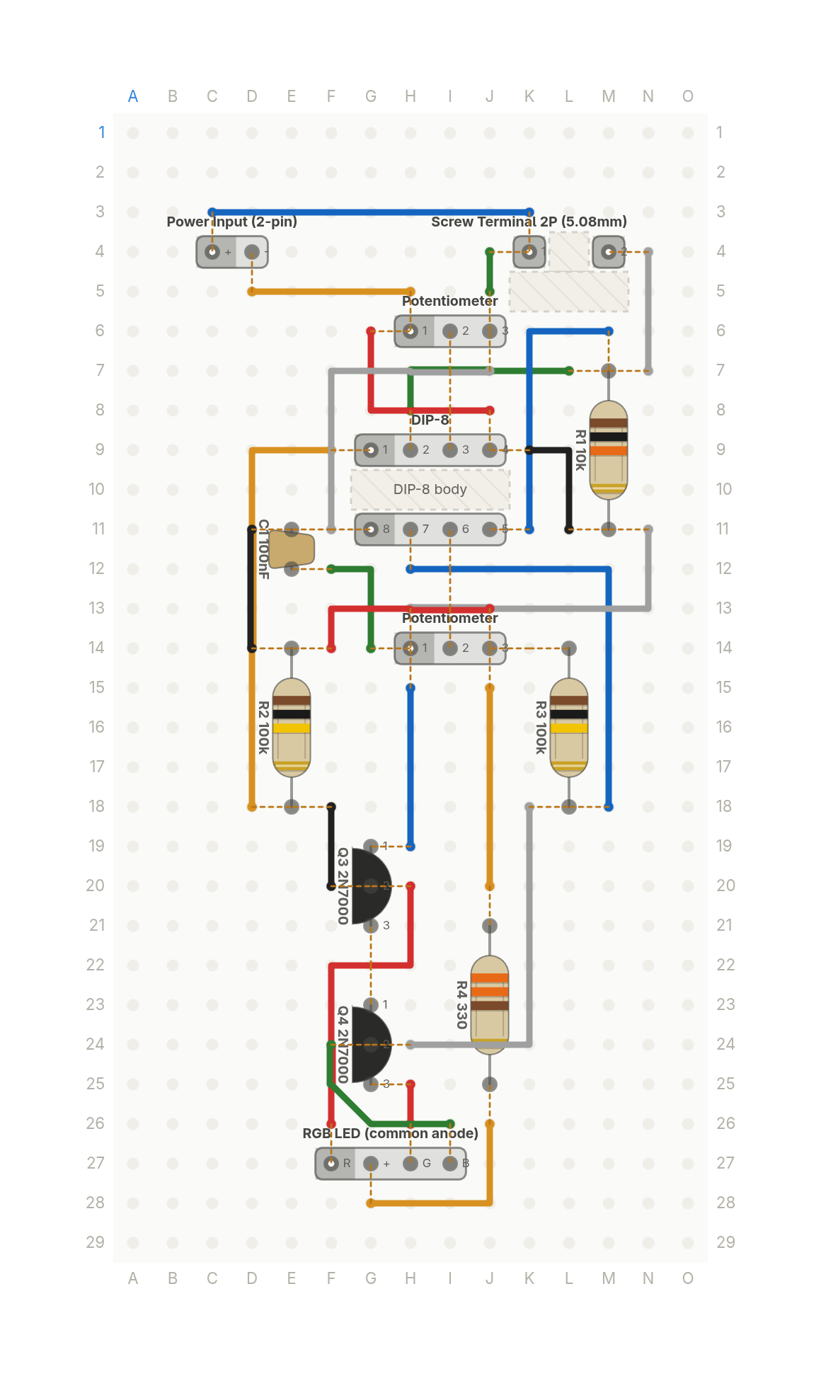 Premieres Oct 13
This LED turns red when the room gets hot
An RGB LED that shows the room temperature: red when it's hot, blue when it's cold, green in between. Two knobs set the limits.
13 parts · 23 wires
SensorsLights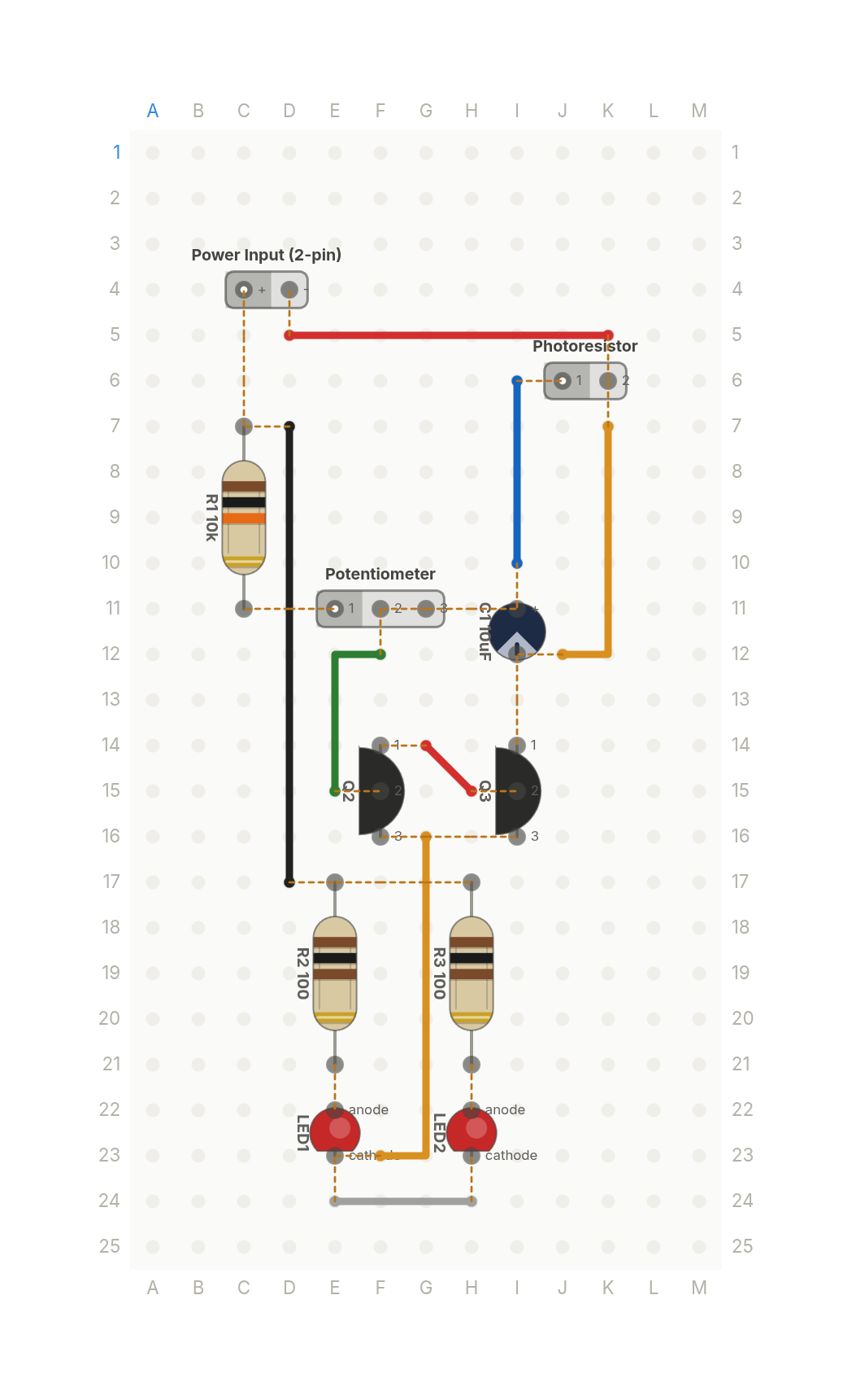 Premieres Oct 26
How does a night light know it's dark?
A night light that switches two LEDs on when the room goes dark. A photoresistor, a trim knob and two transistors.
11 parts · 8 wires
SensorsLights