
An H-bridge with no chip
Four transistors and four diodes that drive a DC motor either way from two control inputs. No driver chip.
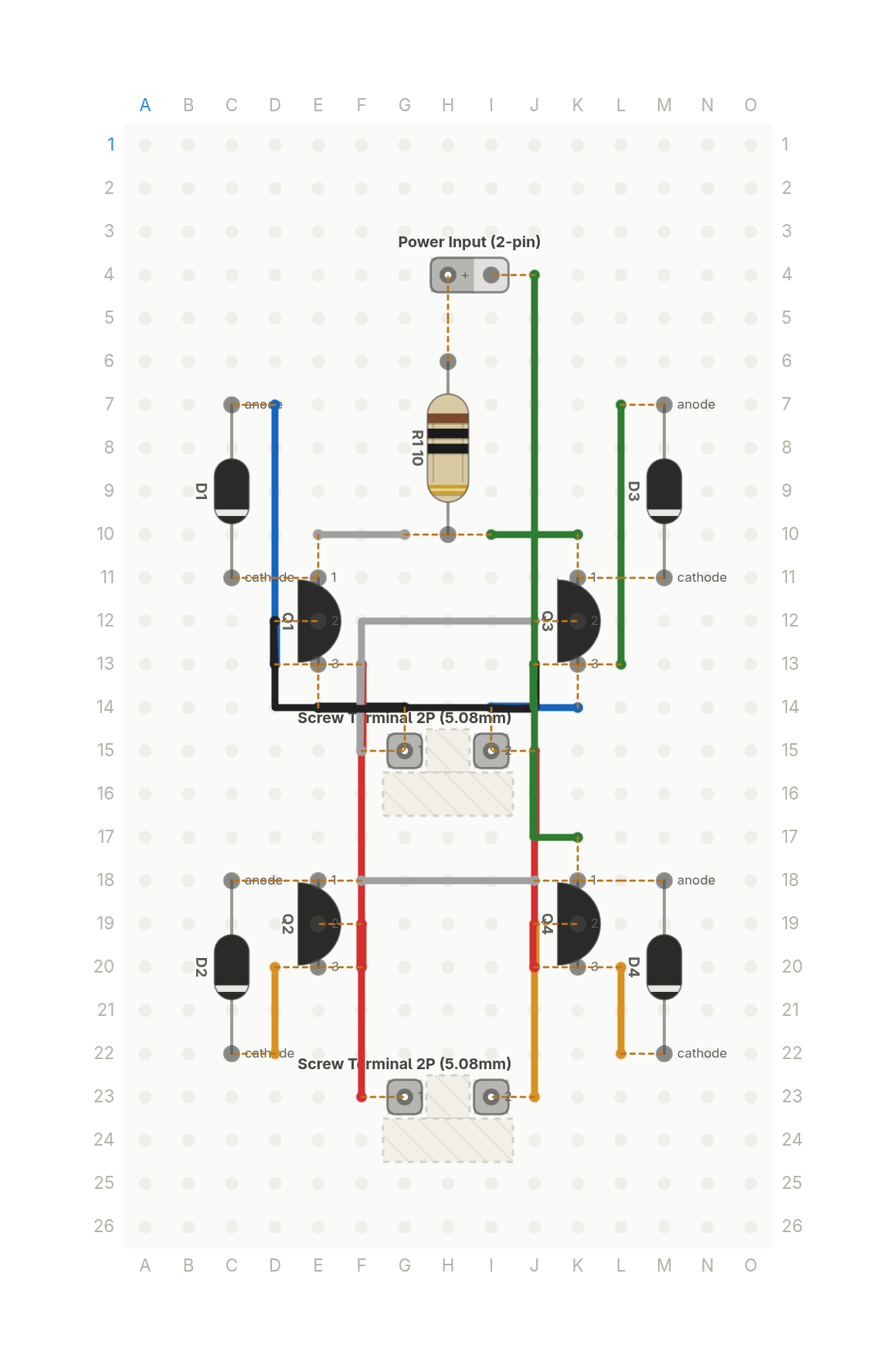
Free build sheet
The parts, every wire with its length and bend points, a bend guide, both sides of the board and checkboxes to track your progress. Print it or keep it open at the bench.
Open the build sheetWhat you need
12 parts on a perfboard 15 × 26 holes, plus hookup wire.
| Qty | Part | Where to buy |
|---|---|---|
| 4 | Diode (axial) D1, D2, D3, D4 | |
| 1 | Power Input (2-pin) J1 | |
| 2 | Screw Terminal 2P (5.08mm) J2, J3 | |
| 2 | PNP Transistor (TO-92) Q1, Q3 | |
| 2 | NPN Transistor (TO-92) Q2, Q4 | Buy NPN Transistor (TO-92) on Amazon |
| 1 | Resistor (axial)10 R1 | Buy Resistor (axial) on Amazon |
Check every pin against the datasheet of the exact part in your hands before wiring.
As an Amazon Associate I earn from qualifying purchases.
Cut list
16 wires, 358 mm (14.1 in) in total, in the order the build sheet cuts them. Wire numbers match the build sheet. Each length includes 5 mm per end to go through the hole.
| Wire | Colour and net | Length | ||
|---|---|---|---|---|
| 6 | BlackOUTA E14 → G14 | E14 → G14 | 15mm | Straight |
| 12 | BlackOUTB J13 → D12 | J13 → D12 | 33mm | 8mm (90°), 23mm (90°) |
| 11 | BlueOUTB K14 → I14 | K14 → I14 | 15mm | Straight |
| 5 | BlueOUTA D7 → D13 | D7 → D13 | 25mm | Straight |
| 4 | GreenVPLUS I10 → K10 | I10 → K10 | 15mm | Straight |
| 10 | GreenOUTB L7 → L13 | L7 → L13 | 25mm | Straight |
| 16 | GreenGND K17 → J4 | K17 → J4 | 46mm | 8mm (90°) |
| 1 | RedIN1 F23 → F19 | F23 → F19 | 20mm | Straight |
| 13 | RedOUTB J15 → J20 | J15 → J20 | 23mm | Straight |
| 7 | RedOUTA F13 → F20 | F13 → F20 | 28mm | Straight |
| 3 | WhiteVPLUS G10 → E10 | G10 → E10 | 15mm | Straight |
| 15 | WhiteGND F18 → J18 | F18 → J18 | 20mm | Straight |
| 9 | WhiteOUTA F15 → J12 | F15 → J12 | 28mm | 13mm (90°) |
| 8 | YellowOUTA D20 → D22 | D20 → D22 | 15mm | Straight |
| 14 | YellowOUTB L20 → L22 | L20 → L22 | 15mm | Straight |
| 2 | YellowIN2 J23 → J19 | J23 → J19 | 20mm | Straight |
About this build
A full H-bridge built from four discrete transistors and no driver chip. Two NPN transistors form the low side, two PNP transistors form the high side, and a DC motor sits across the two outputs on a screw terminal.
The trick is the cross coupling. When an input goes high, its low side transistor pulls that output toward ground, and the falling output switches on the high side transistor on the diagonally opposite leg. So input one drives the motor one way, input two drives it the other way, and two control signals are all you need.
Four flyback diodes, one across each transistor, catch the kick from the motor winding. A 10 ohm series resistor on the supply keeps stall current in check.
This layout leaves out the base resistors to keep the board readable, so treat it as a routing study, not a finished driver. A real build needs a base current limiting resistor on every transistor.
More builds
See all builds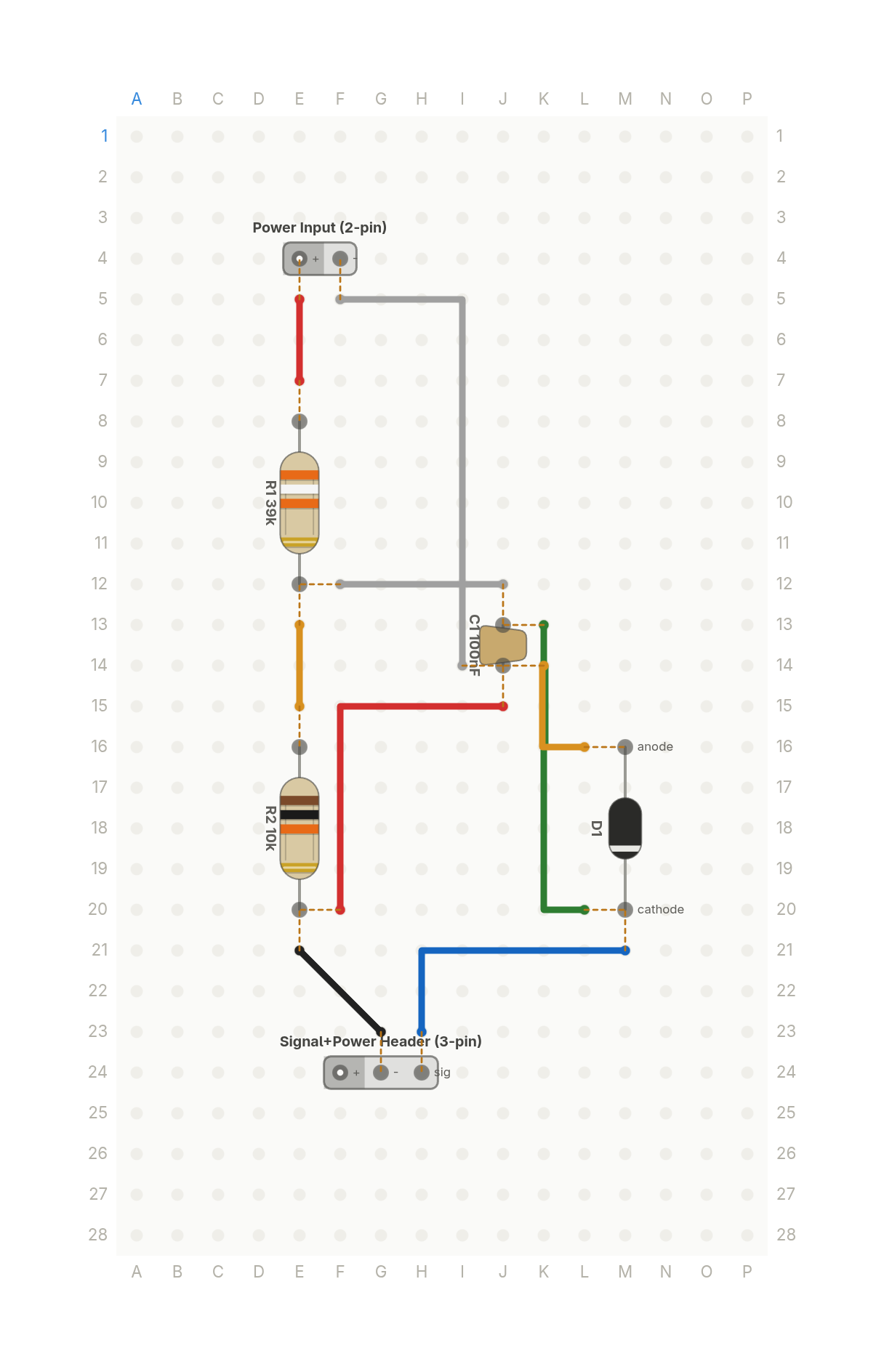 Video
VideoHow your ESP32 reads a 12V battery: the voltage divider
Two resistors scale a 12V battery down to a voltage an ESP32's 3.3V input can read safely, with a zener as a backstop.
6 parts · 9 wires
PowerSensors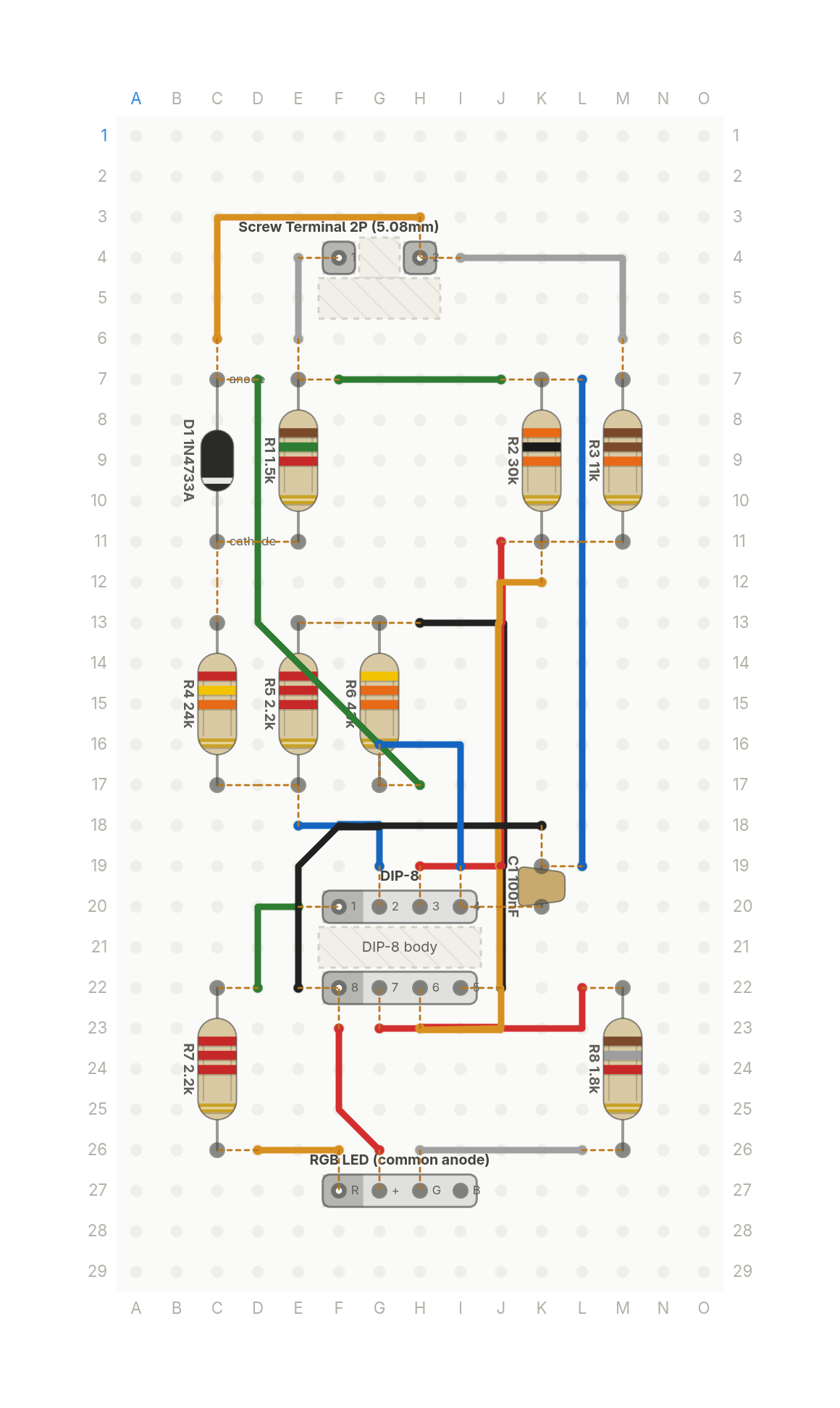 Video
VideoThis LED tells you how dead your battery is
A light for a 12V lead acid battery: green when it's healthy, yellow when it's getting low, red when it's nearly flat.
13 parts · 17 wires
PowerTools and test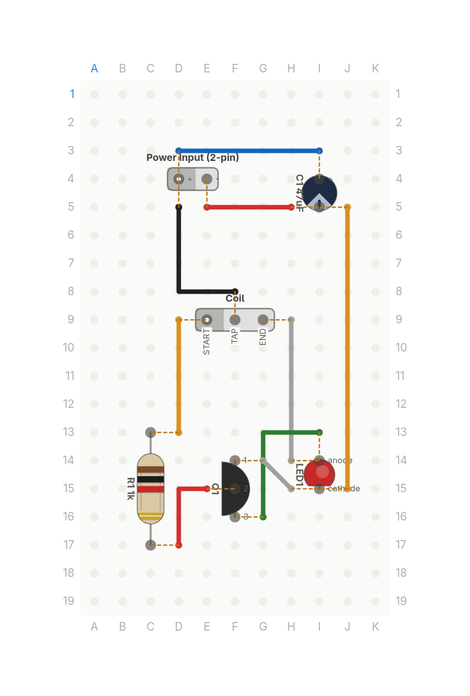 Video
VideoThis lights an LED from a dead battery
One transistor and a hand wound coil that light a white LED from a nearly dead 1V cell. Six parts.
6 parts · 9 wires
LightsPower