
The most famous chip in electronics
The 555 timer doing its classic job: blinking an LED about once a second. A good first build.
Free build sheet
The parts, every wire with its length and bend points, a bend guide, both sides of the board and checkboxes to track your progress. Print it or keep it open at the bench.
Open the build sheetWhat you need
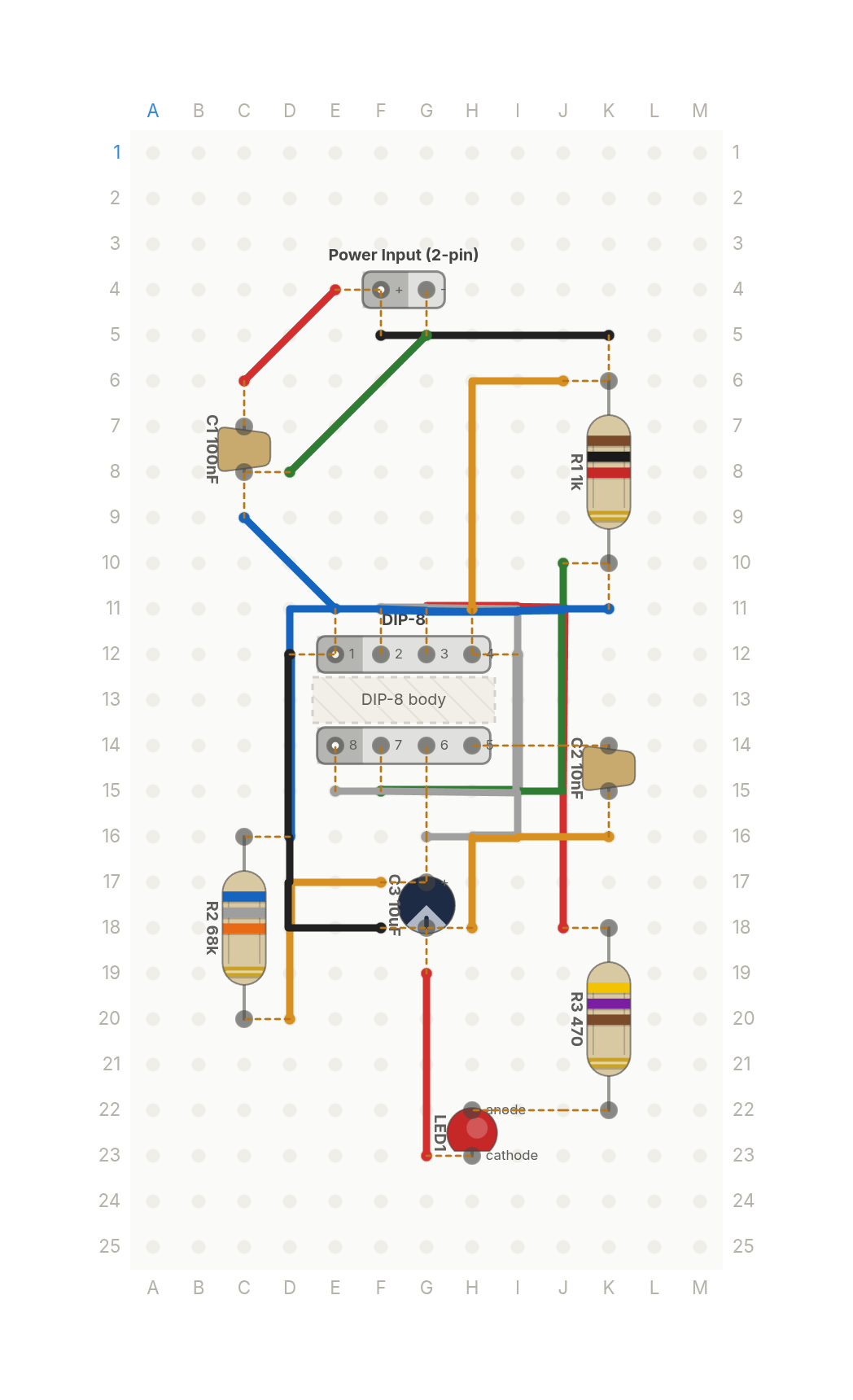
9 parts on a perfboard 13 × 25 holes, plus hookup wire.
| Qty | Part | Where to buy |
|---|---|---|
| 1 | Ceramic Cap100nF C1 | Buy Ceramic Cap on Amazon |
| 1 | Ceramic Cap10nF C2 | Buy Ceramic Cap on Amazon |
| 1 | Electrolytic Cap10uF C3 | Buy Electrolytic Cap on Amazon |
| 1 | Power Input (2-pin) J1 | |
| 1 | LED LED1 | Buy LED on Amazon |
| 1 | Resistor (axial)1k R1 | Buy Resistor (axial) on Amazon |
| 1 | Resistor (axial)68k R2 | Buy Resistor (axial) on Amazon |
| 1 | Resistor (axial)470 R3 | Buy Resistor (axial) on Amazon |
| 1 | DIP-8 U1 |
Check every pin against the datasheet of the exact part in your hands before wiring.
As an Amazon Associate I earn from qualifying purchases.
Cut list
14 wires, 373 mm (14.7 in) in total, in the order the build sheet cuts them. Wire numbers match the build sheet. Each length includes 5 mm per end to go through the hole.
| Wire | Colour and net | Length | ||
|---|---|---|---|---|
| 6 | BlackVCC K5 → F5 | K5 → F5 | 23mm | Straight |
| 12 | BlackGND D12 → F18 | D12 → F18 | 30mm | 20mm (90°) |
| 11 | BlueGND C9 → E11 | C9 → E11 | 17mm | Straight |
| 5 | BlueDISCH K11 → D16 | K11 → D16 | 40mm | 23mm (90°) |
| 10 | GreenGND G5 → D8 | G5 → D8 | 21mm | Straight |
| 4 | GreenDISCH J10 → F15 | J10 → F15 | 33mm | 18mm (90°) |
| 7 | RedVCC E4 → C6 | E4 → C6 | 17mm | Straight |
| 13 | RedGND G19 → G23 | G19 → G23 | 20mm | Straight |
| 1 | RedOUT J18 → G11 | J18 → G11 | 35mm | 23mm (90°) |
| 9 | WhiteVCC I12 → E15 | I12 → E15 | 28mm | 13mm (90°) |
| 3 | WhiteTIMING G16 → F11 | G16 → F11 | 35mm | 10mm (90°), 23mm (90°) |
| 2 | YellowTIMING D20 → F17 | D20 → F17 | 23mm | 13mm (90°) |
| 14 | YellowGND H18 → K16 | H18 → K16 | 23mm | 10mm (90°) |
| 8 | YellowVCC J6 → H11 | J6 → H11 | 28mm | 10mm (90°) |
About this build
The 555 timer is the most famous chip in electronics, and this is its classic job: blinking an LED about once a second.
A 10uF capacitor charges through a 1k and a 68k resistor and discharges through the 68k, and the 555 flips its output every time the capacitor crosses one of its thresholds. The output drives the LED through a 470 ohm resistor.
Two small caps keep it steady, a 100nF across the supply and a 10nF on the control input. It runs from 9V, laid out from the input at the top down to the LED at the bottom.
More builds
See all builds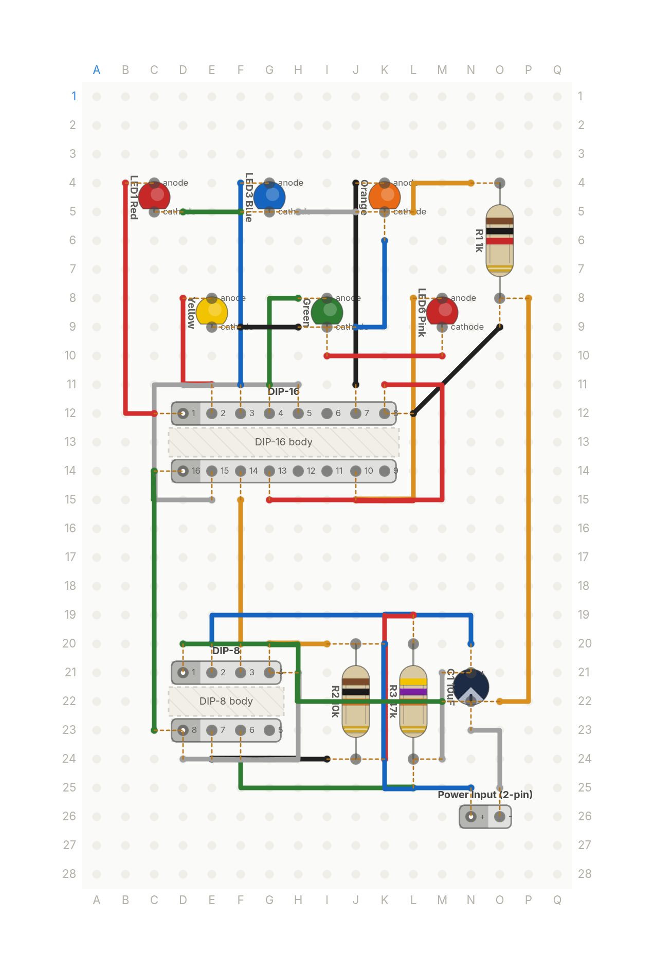 Video
VideoThe Stranger Things light wall, from two chips
Six coloured LEDs light one at a time in a loop, like the Christmas light wall in Stranger Things. A 555 timer and a counter.
13 parts · 28 wires
LightsTimers and logic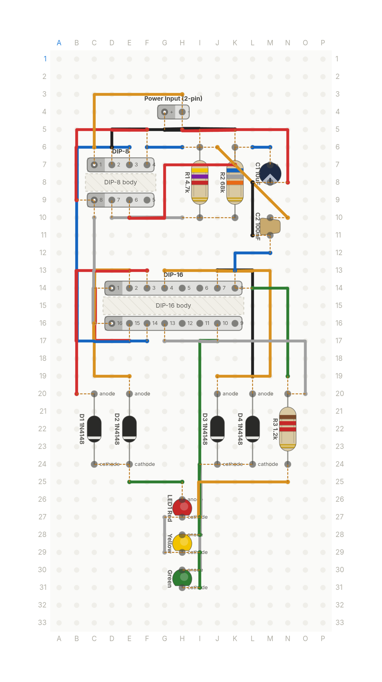 Video
VideoA traffic light that counts to five
Red, yellow and green LEDs that cycle like a traffic light on their own. A 555 timer, a decade counter and four diodes.
15 parts · 27 wires
LightsTimers and logic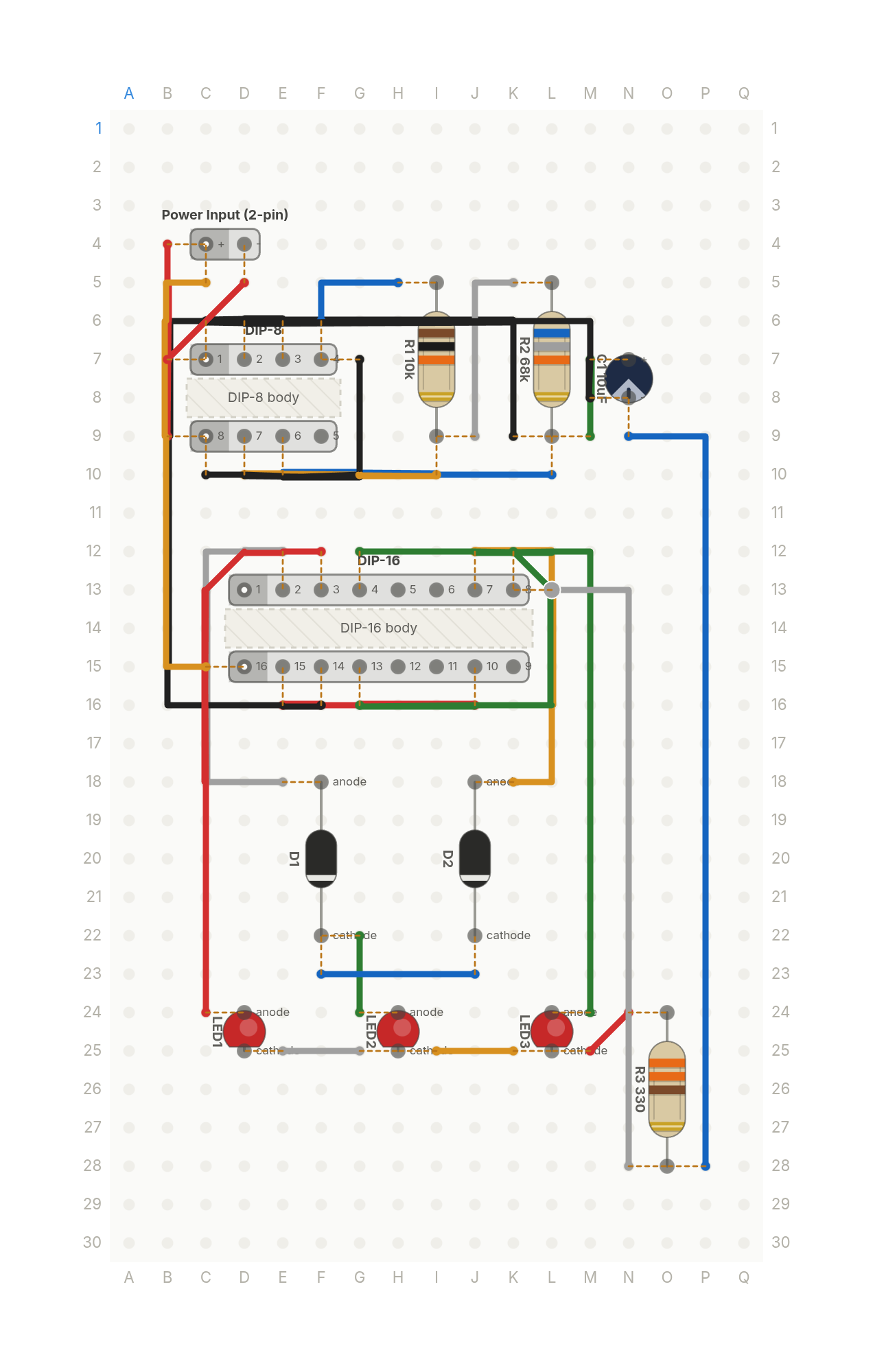 Video
VideoKITT's scanner from two chips
The sweeping eye from KITT in Knight Rider, from a 555 timer, a decade counter and two steering diodes.
12 parts · 25 wires
LightsTimers and logic