
I replaced three chips with one
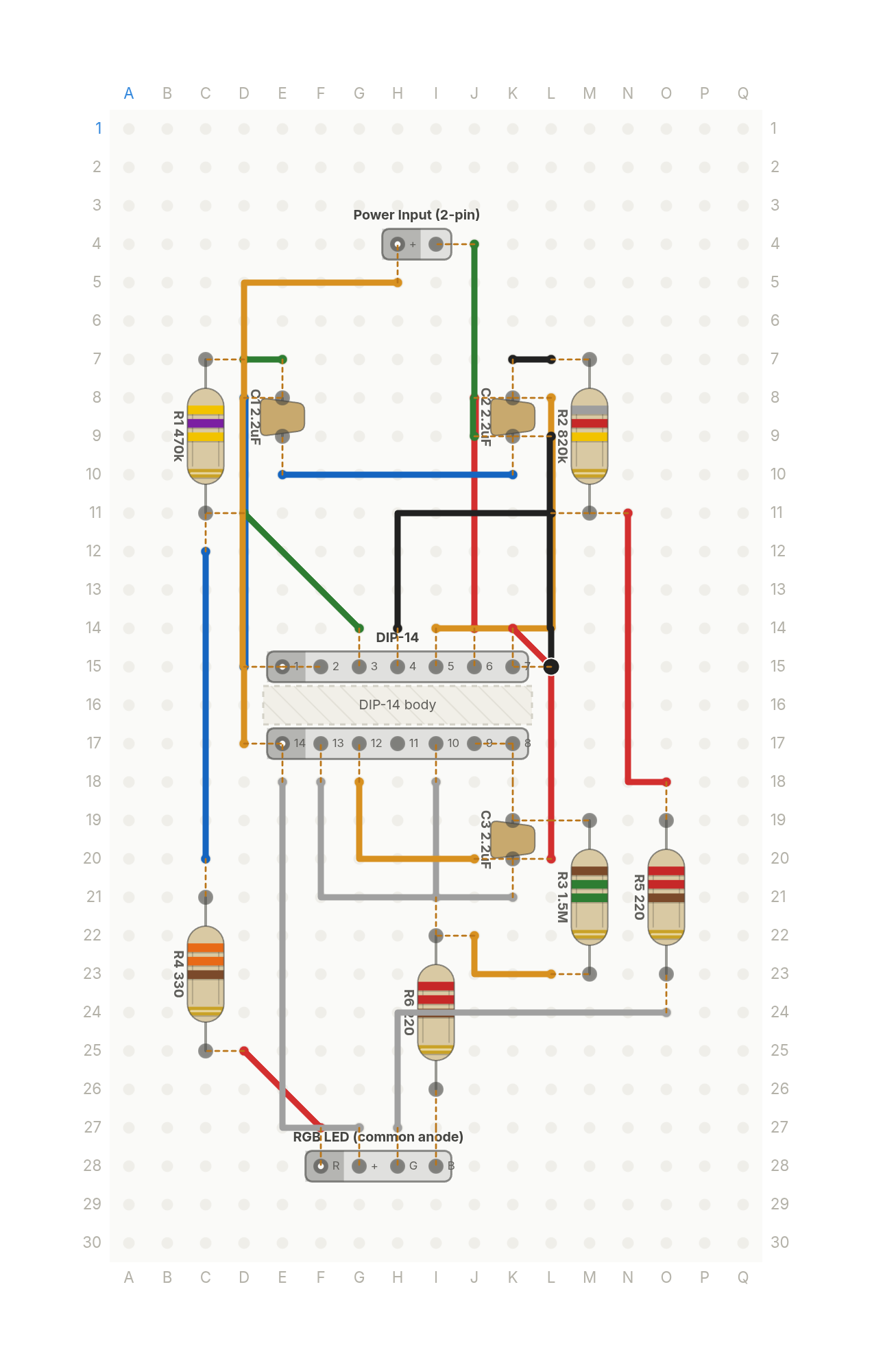
The chaos lamp again, but one CD4093B chip replaces three 555s, blinking an RGB LED's colours at rates that never line up.
Free build sheet
The parts, every wire with its length and bend points, a bend guide, both sides of the board and checkboxes to track your progress. Print it or keep it open at the bench.
Open the build sheetWhat you need
12 parts on a perfboard 17 × 30 holes, plus hookup wire.
| Qty | Part | Where to buy |
|---|---|---|
| 3 | Ceramic Cap2.2uF C1, C2, C3 | Buy Ceramic Cap on Amazon |
| 1 | Power Input (2-pin) J1 | |
| 1 | RGB LED (common anode) Q1 | Buy RGB LED (common anode) on Amazon |
| 1 | Resistor (axial)470k R1 | Buy Resistor (axial) on Amazon |
| 1 | Resistor (axial)820k R2 | Buy Resistor (axial) on Amazon |
| 1 | Resistor (axial)1.5M R3 | Buy Resistor (axial) on Amazon |
| 1 | Resistor (axial)330 R4 | Buy Resistor (axial) on Amazon |
| 2 | Resistor (axial)220 R5, R6 | Buy Resistor (axial) on Amazon |
| 1 | DIP-14 U1 |
Check every pin against the datasheet of the exact part in your hands before wiring.
As an Amazon Associate I earn from qualifying purchases.
Cut list
21 wires, 549 mm (21.6 in) in total, in the order the build sheet cuts them. Wire numbers match the build sheet. Each length includes 5 mm per end to go through the hole.
| Wire | Colour and net | Length | ||
|---|---|---|---|---|
| 6 | BlackOSC2 L7 → K7 | L7 → K7 | 13mm | Straight |
| 18 | BlackGND L9 → L15 | L9 → L15 | 25mm | Straight |
| 12 | BlackOUT2 L11 → H14 | L11 → H14 | 28mm | 15mm (90°) |
| 17 | BlueGND K10 → E10 | K10 → E10 | 25mm | Straight |
| 5 | BlueOSC1 D8 → D15 | D8 → D15 | 28mm | Straight |
| 11 | BlueOUT1 C12 → C20 | C12 → C20 | 30mm | Straight |
| 4 | GreenOSC1 D7 → E7 | D7 → E7 | 13mm | Straight |
| 10 | GreenOUT1 D11 → G14 | D11 → G14 | 21mm | Straight |
| 16 | GreenGND J4 → J9 | J4 → J9 | 23mm | Straight |
| 1 | RedRED D25 → F27 | D25 → F27 | 17mm | Straight |
| 7 | RedOSC2 J8 → J14 | J8 → J14 | 25mm | Straight |
| 19 | RedGND K14 → L20 | K14 → L20 | 26mm | 9mm (45°) |
| 13 | RedOUT2 N11 → O18 | N11 → O18 | 30mm | 23mm (90°) |
| 3 | WhiteOUT3 I21 → I18 | I21 → I18 | 18mm | Straight |
| 21 | WhiteGND K21 → F18 | K21 → F18 | 30mm | 18mm (90°) |
| 9 | WhiteGRN O24 → H27 | O24 → H27 | 35mm | 23mm (90°) |
| 15 | WhiteVDD E18 → G27 | E18 → G27 | 38mm | 28mm (90°) |
| 2 | YellowOUT3 L23 → J22 | L23 → J22 | 18mm | 10mm (90°) |
| 20 | YellowGND J20 → G18 | J20 → G18 | 23mm | 13mm (90°) |
| 8 | YellowOSC2 L8 → I14 | L8 → I14 | 33mm | 20mm (90°) |
| 14 | YellowVDD H5 → D17 | H5 → D17 | 51mm | 15mm (90°) |
About this build
A chaos lamp usually takes three 555 timers, one per colour. This one does the whole thing with a single CD4093B, a quad 2 input Schmitt trigger NAND.
Three of its four gates each become an RC oscillator. Tie a gate's two inputs together and it acts as an inverter. Run a resistor from the output back to the input and a capacitor from the input to ground, and it oscillates. Each gate gets a different resistor, 470k, 820k and 1.5M, all on 2.2uF caps, so the three blink rates never line up and the common anode RGB LED drifts through colour mixes.
Each oscillator drives one colour through its own series resistor, a 330 and two 220s. The fourth gate isn't used, so its inputs are tied to ground instead of left floating, which is the right thing to do with any unused CMOS input. Power comes in on a 2 pin input, anywhere from 5V to 15V.
More builds
See all builds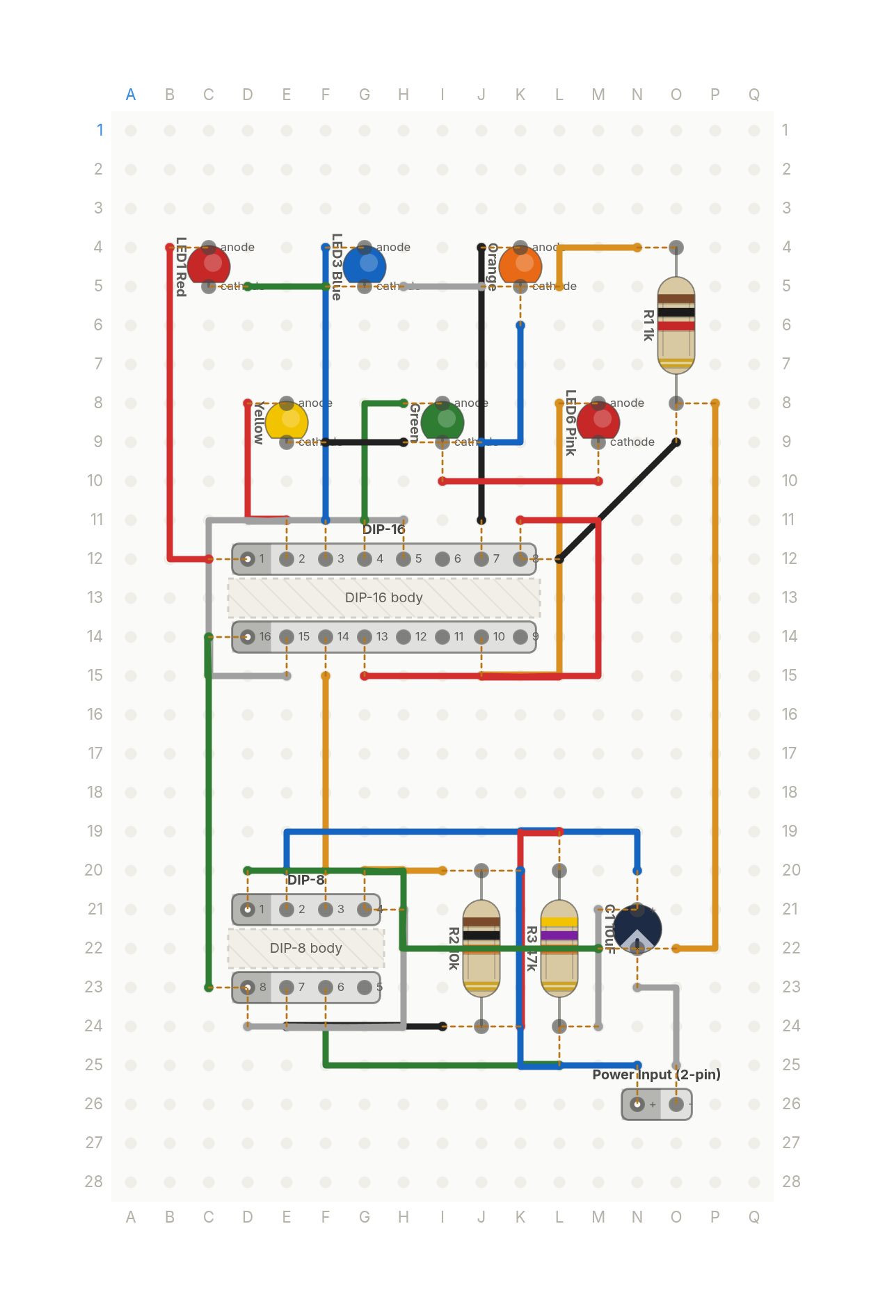 Video
VideoThe Stranger Things light wall, from two chips
Six coloured LEDs light one at a time in a loop, like the Christmas light wall in Stranger Things. A 555 timer and a counter.
13 parts · 28 wires
LightsTimers and logic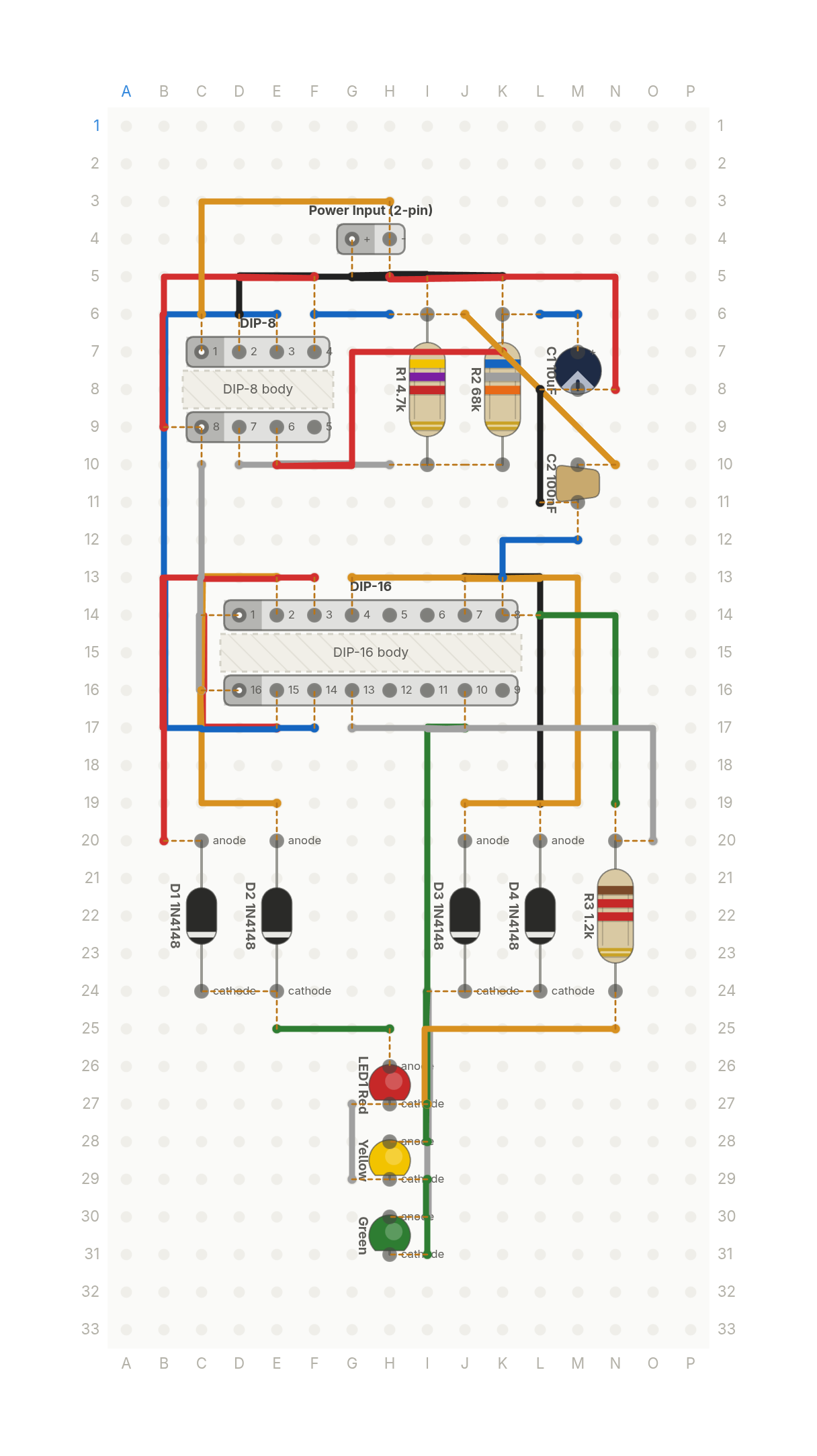 Video
VideoA traffic light that counts to five
Red, yellow and green LEDs that cycle like a traffic light on their own. A 555 timer, a decade counter and four diodes.
15 parts · 27 wires
LightsTimers and logic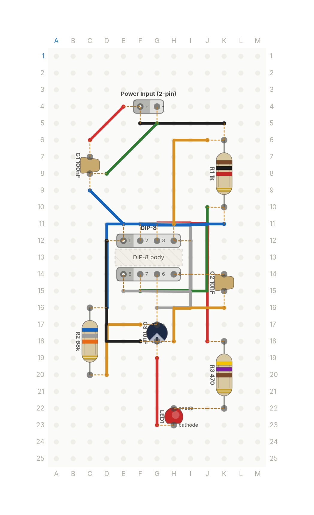 Video
VideoThe most famous chip in electronics
The 555 timer doing its classic job: blinking an LED about once a second. A good first build.
9 parts · 14 wires
Timers and logicLights