
It tells me how full the tank is
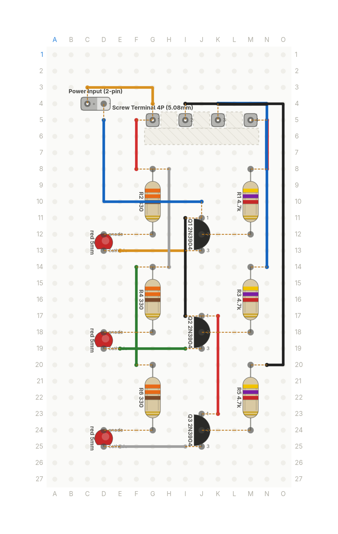
Three LEDs stacked like the tank they watch: each one lights when the water reaches its probe. Three transistors, no chip.
Free build sheet
The parts, every wire with its length and bend points, a bend guide, both sides of the board and checkboxes to track your progress. Print it or keep it open at the bench.
Open the build sheetWhat you need
14 parts on a perfboard 15 × 27 holes, plus hookup wire.
| Qty | Part | Where to buy |
|---|---|---|
| 1 | Power Input (2-pin) J1 | |
| 1 | Screw Terminal 4P (5.08mm) J2 | |
| 3 | LEDred 5mm LED1, LED2, LED3 | Buy LED on Amazon |
| 3 | NPN Transistor (TO-92)2N3904 Q1, Q2, Q3 | Buy NPN Transistor (TO-92) on Amazon |
| 3 | Resistor (axial)4.7k R1, R3, R5 | Buy Resistor (axial) on Amazon |
| 3 | Resistor (axial)330 R2, R4, R6 | Buy Resistor (axial) on Amazon |
Check every pin against the datasheet of the exact part in your hands before wiring.
As an Amazon Associate I earn from qualifying purchases.
Cut list
13 wires, 369 mm (14.5 in) in total, in the order the build sheet cuts them. Wire numbers match the build sheet. Each length includes 5 mm per end to go through the hole.
| Wire | Colour and net | Length | ||
|---|---|---|---|---|
| 12 | BlackGND I11 → I17 | I11 → I17 | 25mm | Straight |
| 6 | BlackPROBE_LOW N20 → I4 | N20 → I4 | 68mm | 8mm (90°), 48mm (90°) |
| 11 | BlueGND D5 → J10 | D5 → J10 | 38mm | 18mm (90°) |
| 5 | BluePROBE_MID N14 → K4 | N14 → K4 | 43mm | 30mm (90°) |
| 4 | GreenCOLL_MID E19 → I19 | E19 → I19 | 20mm | Straight |
| 10 | GreenVCC F14 → F20 | F14 → F20 | 25mm | Straight |
| 1 | RedPROBE_HI N8 → N5 | N8 → N5 | 18mm | Straight |
| 7 | RedVCC F8 → F5 | F8 → F5 | 18mm | Straight |
| 13 | RedGND K17 → K23 | K17 → K23 | 25mm | Straight |
| 3 | WhiteCOLL_LOW E25 → I25 | E25 → I25 | 20mm | Straight |
| 9 | WhiteVCC H8 → H14 | H8 → H14 | 25mm | Straight |
| 2 | YellowCOLL_HI E13 → I13 | E13 → I13 | 20mm | Straight |
| 8 | YellowVCC G4 → C3 | G4 → C3 | 23mm | 8mm (90°) |
About this build
A tank level indicator built from three identical transistor bands. Three bare wire probes hang at three heights in the tank, and a fourth probe at the bottom is the common, sitting at 5V.
Water conducts a little, so when it reaches a probe it pulls that band's 2N3904 base up through a 4.7k resistor, and the band's red LED lights through its 330 ohm resistor. The LEDs are stacked on the board low at the bottom and high at the top, so the board reads like the tank.
DC through bare probes corrodes them over time, so treat this as a demo, not a permanent install. The probes connect on a 4 pin screw terminal and 5V comes in on a 2 pin input.
More builds
See all builds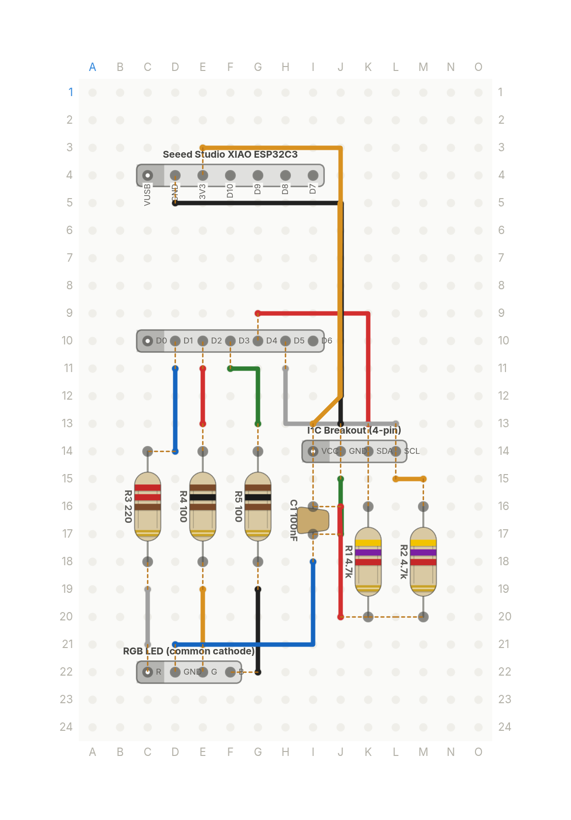 Video
VideoThe whole weather station is three parts
A XIAO ESP32C3 reads a temperature and humidity sensor and shows the reading as a colour on an RGB LED.
9 parts · 14 wires
Sensors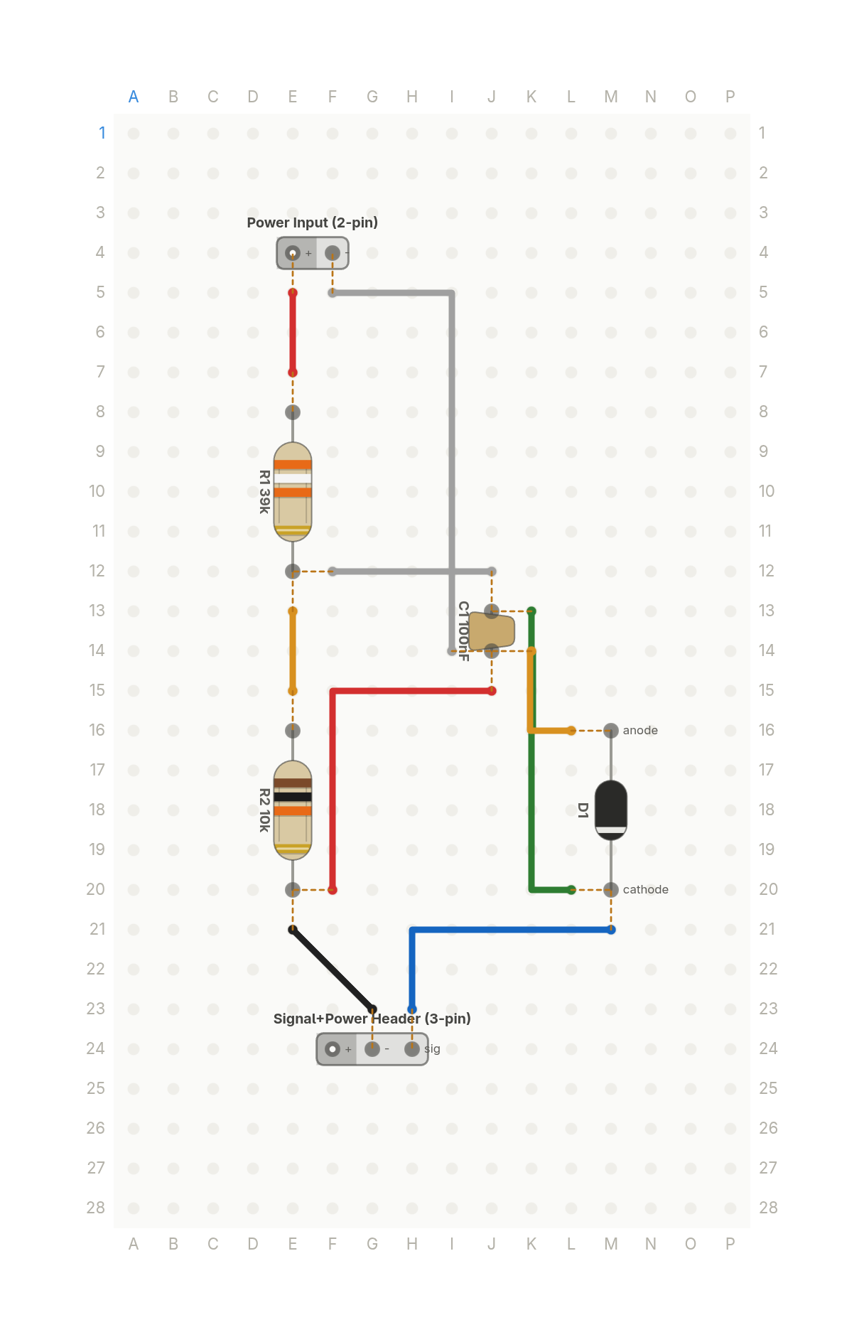 Video
VideoHow your ESP32 reads a 12V battery: the voltage divider
Two resistors scale a 12V battery down to a voltage an ESP32's 3.3V input can read safely, with a zener as a backstop.
6 parts · 9 wires
PowerSensors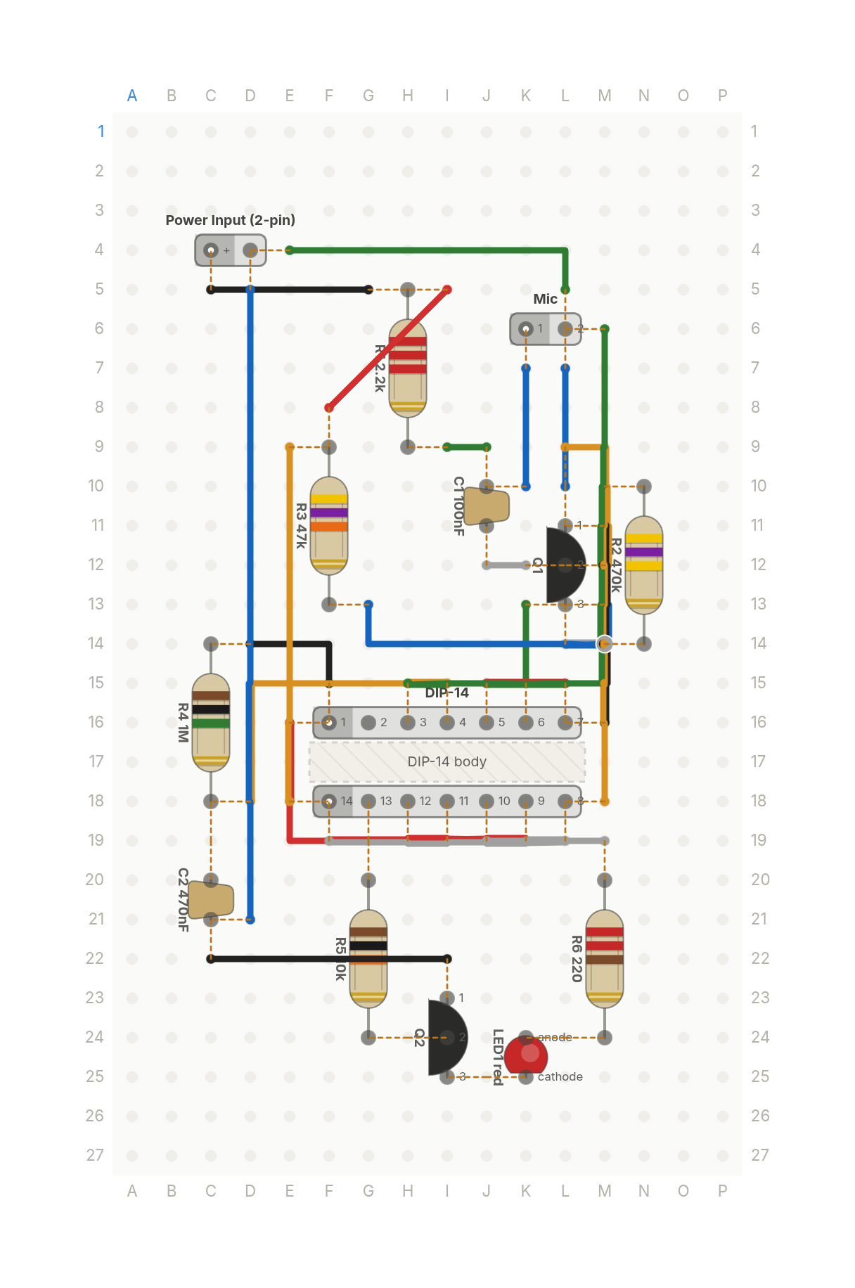 Video
VideoThe Clapper, recreated: lights that turn on when you clap
Clap once and an LED turns on, clap again and it turns off. A microphone, two transistors and one flip-flop chip.
14 parts · 24 wires
SensorsLights